Alky Deisobutanizer Optimization
Analysis of Alky unit DIB exposes design and operating considerations
As refiners strive to increase unit production or accommodate feed composition changes with minimal capital investment, existing equipment design and operations should be evaluated for opportunities to improve efficiency.
In many cases, throughput limitations can be resolved through review and modification of existing equipment design.
A recent examination of an alkylation plant deisobutanizer (DIB) illustrates design and operating considerations that should be addressed when capacity increases and efficiency improvements are desired.
This sulfuric acid alkylation plant had excess feed and reaction zone capacity. The DIB was the limiting factor; specifically, the DIB reboiler duty was at its maximum and the reboiler steam-supply valves were wide open. A new alkylate Rvp specification of 5.0 psia also was constraining operation.
An engineering review suggested minor design modifications and maintenance items which, when implemented, increased alkylate production capacity by more than 25%.
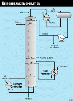
DIB Operation
The alkylation unit is fed isobutane and olefinic C4s, which react in a sulfuric acid catalyst to produce C8+ alkylate. In addition to alkylate, the reactor effluent contains excess isobutane, n-butane, and residual olefinic C4s. This stream is sent to the DIB after caustic and water washing.
Figure 1 shows the DIB flow scheme.
The DIB feed is fractionated into three products:
- Isobutane in the column overhead is recycled to the alkylation reaction section.
- Alkylate in the column bottoms is sent to gasoline blending.
- Normal butane is removed in a vapor side draw.
It should be noted that many units utilize a separate debutanizer column to separate n-butane from alkylate.
Table 1 details the DIB operating statistics for this unit. Data representive of initial operation were collected during the winter months.
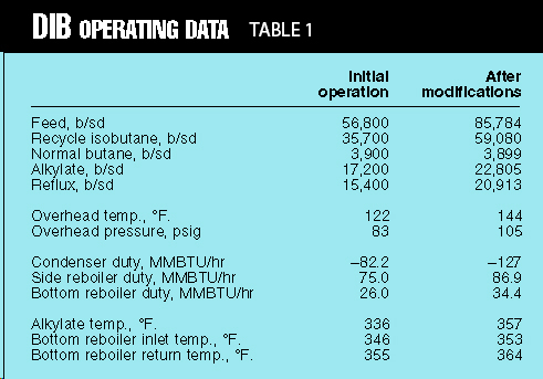
Because the tower was reboiler-limited but was not flooding, the column pressure was reduced during this period. The overhead condensing capacity did not limit operations at the lower pressure because the cooling water temperatures were cooler than the summer design values.
The reduced column pressure mitigated the reboiler limitation, and allowed unit charge rates to be increased somewhat, to the level shown in Table 1.
Even at the lower column pressure, the DIB limited unit operation and the reboiler steam-supply valves remained wide open. Additionally, during the summer, higher cooling water temperatures would eliminate the option to decrease column pressure.
With the help of unit personnel, the authors gathered and analyzed the unit operating data. The data revealed two major areas of concern:
- The 250 psig steam supply to the bottom reboiler had about 70° F. of superheat.
- More important, the bottom-reboiler inlet temperature was 10° F. greater than the alkylate product temperature.
The temperature difference between the reboiler inlet and alkylate product suggested that a significant amount of bottom tray liquid was bypassing the reboiler inlet and going directly to the product side of the bottom baffle.
Review of the tower internals showed that the designers attempted to ensure that liquid from the bottom tray would feed the reboiler preferentially. In operation, however, this was not always occurring.
Further analysis of the operating data revealed reboiler heat-transfer coefficients that were significantly less than design. Coefficients in this range indicated fouling.
Reboiler Review
Thermosyphon reboilers are either once-through or recirculated. The outlet from a once-through thermosyphon returns to the column so that none of its liquid effluent enters the reboiler inlet sump. This is usually accomplished by returning the effluent to the column below the inlet draw location.
The inlet temperature to a once-through reboiler is less than that of a recirculated reboiler in the same service. The lower inlet temperature increases the temperature driving force, as defined by log mean temperature difference (LMTD), and therefore yields a greater duty for the same area.
A once-through reboiler functions as about one theoretical stage in the tower. Recirculated thermosyphons return their outlet to the column so that part of their liquid effluent returns to the reboiler inlet, where it is mixed with light feed from the tray above. Recirculating a thermosyphon has the advantage of lowering the percent vapor of the reboiler outlet.
Thermosyphon reboilers typically are limited to an outlet vapor content of 30-50 wt % to reduce the potential for liquid slugging and to provide a liquid wash for the tube surface. Increasing the concentration of reboiler effluent liquid in the reboiler feed reduces the outlet vapor fraction.
Recirculation also can help ensure a consistent liquid height feeding the thermosyphon. Having a constant liquid head on the reboiler inlet generally results in more stable reboiler operation.
Recirculating a thermosyphon, however, increases equipment size because of the higher flow rates and lower temperature driving forces. The lower driving forces result from the mixed feed entering the reboiler at a higher temperature than if it were fed from only the tray above.
A recirculated thermosyphon equates to some fraction of a theoretical stage. Recirculated thermosyphons are often designed such that, although there is recirculation from the exchanger outlet to its inlet, all of the light liquid from the tray above is preferentially fed to the reboiler. This minimizes the reboiler inlet temperature, thereby maximizing the temperature driving force and the exchanger duty for a given heat-transfer area.
Preferentially feeding the liquid to the reboiler typically is accomplished by installing appropriate internal baffles to direct the light liquid flow to the reboiler inlet.
For the case reviewed here, the side reboilers were not designed for preferential flow. The bottom reboiler was of preferential design, but the internals did not guarantee that the bottom tray liquid would be preferentially fed to the reboiler.
As discussed previously, the initial operating data indicated that the DIB reboiler inlet temperature was higher than that of the DIB bottoms product (alkylate). This surprising observation was checked and rechecked.
The lower product temperature indicated that a large portion of the light liquid feed to the reboiler was bypassing the reboiler inlet and leaving the column directly with the alkylate. The primary effect of this would be to increase the inlet temperature of the bottom reboiler, thereby lowering the temperature driving force and capacity of the exchanger.
The authors developed a process simulation to match the operating data.
In most tower simulations, it is not critical that the reboiler be modeled exactly. Usually, the reboiler duty is simply added to the bottom stage.
In this case, however, to accurately model the existing tower and match the plant data, the process simulation had to include bypass of the reboiler inlet and the appropriate reboiler recirculation rate.
The simulation matched the plant data by sending 50% of the light liquid from the bottom tray directly to the alkylate product. This means half the normal reboiler feed did not enter the exchanger.
The simulation verified that the observed plant temperatures and the theorized bypassing were valid.
The bypassing had several detrimental effects on reboiler performance. It reduced the separation efficiency of the reboiler to much less than one theoretical stage. More important, with half of the bottom tray liquid being sent to product, the reboiler temperatures had to be greatly increased to maintain the alkylate RVP specification.
Essentially, the bottom tray material almost had to meet the RVP specification, and the reboiler outlet had to exceed the specification.
The higher reboiler temperatures reduced the reboiler LMTD and, hence, available duty by almost 40%. The effect was dramatic because of the large volatility difference between n-butane and C8 alkylate.
The lower concentration of butane in the reboiler feed also reduced the heat-transfer coefficient.
The DIB side reboiler also is recirculated, and the design does not attempt to feed preferentially. The exchanger operating conditions, however, are such that the negative effect on exchanger capacity is not as great as it is for the bottom reboiler.
For this reboiler, the narrower differences between the adjacent tray temperatures and compositions lead to a smaller LMTD penalty for bypassing the side reboiler. Calculations suggest that only 5% of the exchanger design capacity is lost because of the nonpreferential feed arrangement.
Superheated Steam
The steam supply to the DIB bottom reboiler had 70° F of superheat. Unfortunately, hotter is not always better for heat transfer.
While this higher steam temperature increased the temperature driving force, it had a negative effect on the heat-transfer coefficient.
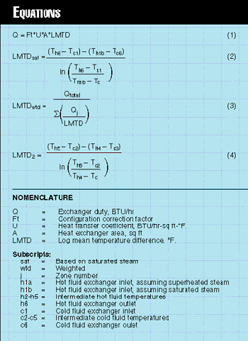
Equation (1) is a common heat-exchanger operating equation (See Equations and Nomenclature). In this equation, the exchanger area and configuration correction factor are multiplied by the LMTD and heat-transfer coefficient to calculate the exchanger duty.
The heat-transfer coefficient varies over the length of the exchanger and is a function of many factors, including fluid physical properties, velocities, and the heat-transfer regime.
Saturated steam condensing on tube surfaces has a very high heat-transfer coefficient. Superheated steam, however, must be cooled to its saturation temperature before it can begin condensing. Much of this cooling occurs through dry-wall desuperheating, for which the heat-transfer coefficient can be 50% or less of the condensing steam heat-transfer coefficient.
Rigorous modeling of this exchanger indicated that the lower heat-transfer coefficients for desuperheating reduced the overall reboiler capacity by about 10%.
Superheated steam also can lead to a mistaken impression about the available temperature driving force.
Figure 2 illustrates typical heating and cooling curves for a steam reboiler. Assuming saturated steam, Equation (2) defines the standard LMTD for points on Figure 2.
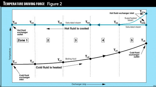
This typical LMTD calculation uses the inlet and outlet temperatures of the heat exchanger. If the steam were superheated, the calculated LMTD would be significantly greater, but this greater value does not reflect exchanger operation accurately. The majority of heat transfer occurs through condensation of saturated steam.
The LMTD calculation also can be skewed because the steam is boiling a fluid. Much of the heat transfer associated with boiling a liquid may occur at a nearly constant temperature. When a fluid boils, the standard LMTD calculation does not accurately reflect the temperature driving force along the length of the exchanger.
To correct for the inaccuracies inherent in the standard LMTD calculation, a weighted LMTD can be used (Equation 3).
Fig. 2 depicts the heating and cooling curves divided into zones. Typically, these zones are in equal-duty increments.
The weighted LMTD is calculated by determining the standard LMTD of each zone, weighting the LMTD by the duty of the zone, then summing these weighted LMTD values. Equation (4) is the LMTD equation for Zone 2.
The greater the number of zones, the more closely the calculated driving force matches actual conditions.
The weighted LMTD accounts for the effects of the unusual temperature curves associated with boiling and condensing fluids and, in this case, for the effects of superheated steam. Replacing the LMTD term in Equation 1 with the weighted LMTD value allows a more accurate exchanger evaluation.
Fouling
Data from the unit were analyzed to calculate heat-transfer coefficients for the overhead condensers and bottom and side reboilers. The coefficient calculated for the overhead condenser matched design very well. The coefficients calculated from unit data for both reboilers, on the other hand, were about 70% of design.
The bottom reboiler’s reduced heat-transfer coefficient is, in part, a result of the dry-wall desuperheating discussed previously. The substantial reduction in heat-transfer coefficient compared to design, however, suggests fouled exchangers.
The original design included typical fouling factors for both reboiler services. The potential fouling that can occur in an alkylation unit as a result of poor reaction-zone conditions or inefficient effluent treating cannot always be accounted for in the final design.
Often it is impractical, or at least costly, to design for unusual or upset operating conditions. Design and construction costs, however, should be weighed against future operating penalties when the design basis is reviewed.
The cure for low heat-transfer coefficients does not necessarily lie in increased surface area for the exchangers at risk. It often is possible to find a less-expensive solution that reduces the likelihood of extreme fouling while improving unit operation.
In this case, the refiner found such opportunities for enhancing operations, although the company may install additional exchanger area in the future.
Improvements
A short plant shutdown was scheduled to implement the following improvements:
- A baffle and modified seal pans were installed in the column to ensure that the bottom tray liquid was preferentially fed to the bottom reboiler
- Both reboilers, found to be fouled, were cleaned
- A steam-header desuperheater was put into service.
The refiner considered modification of internals to provide preferential feed to the side reboiler. These changes were deferred because of the complexity of their design and installation, and because they were expected to have relatively minor impact.
Revised Operation
After implementing these improvements, unit performance improved. Post-revamp operation is detailed in Table 1.
DIB charge increased almost 29,000 b/d, allowing an increase in alkylate production of 5,600 b/d, or 32.6%.
The column now has a more typical bottoms temperature profile-the reboiler inlet temperature is lower than the column bottoms product temperature. Additionally, the calculated reboiler heat-transfer coefficients are at design levels.
Examination of existing operating conditions and equipment design often reveal opportunities for higher throughput, improved operation, and increased profits. Although further investigation may indicate that new equipment is required, relatively minor changes often lead to large increases in unit performance and profitability.
The Authors
Joseph Musumeci is a consultant with Ascent Engineering. Previously he was vice-president of MPEC Inc. and worked as a process engineer for Amoco Oil Co. He has a BS in chemical engineering from Texas A&M University. He is a registered professional engineer in Texas. He is also a pilot.
Rick Chavez is president of Chavez Consulting Inc. in Dallas. Previously, he was a consultant for Turner, Mason & Co., and has worked for Lyondell Petrochemical Co., El Paso Refining Co. Ltd., Stratco Inc., and Amerada Hess Corp. He holds a BS in chemical engineering from Colorado School of Mines.
Donald F. Schneider is a consultant with Stratus Engineering Inc. in Houston. Previously, he was a senior engineer for Stone & Webster Engineering Corp. and an operating and project engineer for Shell Oil Co. He has a BS from the University of Missouri at Rolla and an MS from Texas A&M University, both in chemical engineering. He is a registered professional engineer in Texas.