
Taking a Holistic Approach to a Revamp
If all aspects of a system are carefully examined, even minor changes can lead to large gains in unit performance and profitability
JOE MUSUMECI and JOHN ESTILL
Ascent Engineering
GREGORY MITCHELL
Shell Norco
Engineers frequently focus on one piece of the puzzle as a cause for poor performance. Blinkers on, fixing that one problem becomes the project goal. A tray specialist will focus on the tray design, a hydraulic engineer will focus on hydraulics, and so on. While some improvement is obtained, many opportunities to yield major benefits can be missed. Instead, a holistic review of the entire plant operation by engineers familiar with all disciplines best identifies and captures the processing opportunities.
A recent review of a butane splitter illustrates how analysing the entire system – trays, reboiler, condenser, controls, and operation – uncovered multiple changes and modifications that, if implemented individually, would each improve isobutane recovery to varying degrees.
Taken together, however, finding and implementing all these changes resulted in a predicted 50% increase in isobutane recovered at design charge rates. A review of postrevamp operation has shown that the modified tower has improved the refinery’s bottom line by at least $2.6 million/y through a combination of improved operating guidelines and capital fixes to existing design issues.
Background
The butane splitter column presented here recovers isobutane from a mixed C4 stream originating in the crude unit saturates gas plant (SGP). The isobutane is used as make-up to the alkylation unit.
The tower was originally built in 1965 for a different service and was converted to butane splitter service later. Diameter limited, the column had been revamped in 1999 with high capacity trays and some additional condensing capacity. The tower had under-performed since that revamp, leaving excess isobutane in the bottom product. This required the refinery to purchase additional isobutane for the alkylation unit and limited the amount of butane that could be blended into gasoline, both of which resulted in a considerable economic penalty.
A study was commissioned a few years after the 1999 revamp to determine the causes of poor separation. Since the trays were changed from conventional valve trays to high capacity trays during the revamp, it was felt that the trays were at fault, and the study focused on the tray design and efficiency. The study presented several recommendations regarding tray design details and proposed the tower be retrayed again. No action was taken at that time.
Several years later, a short column outage was planned that would allow potential modifications to improve tower performance. Ascent Engineering was asked to review the previous study and other, more recent troubleshooting efforts and propose modifications that would improve the tower performance. Based on the previous study, new trays were an expected recommendation. Reboiler performance was a known issue. The upcoming shutdown was expected to be short, and the time allotted would not allow for the installation of new major equipment such as a new reboiler. Tie-ins for new equipment could be made if necessary. Because the shutdown had already been scheduled prior to the project kick-off, the new study was fast tracked in order to meet the already planned shutdown window.
The project methodology Ascent used was not only to focus on the tower trays, as was previously done, but to take a holistic approach to look at the entire system. This was particularly important since the tower had been designed for a different service, and some aspects of the equipment layout may not have been ideally suited for butane splitter service. Ascent started with a very detailed plant match simulation and evaluation of all major system components to identify deficiencies and opportunities. Verifying the reboiler, the condenser, the controls, the operating philosophy, and the other tower internals in addition to the trays was required if the project was to be a success.
Butane Splitter Operation
As Figure 1 shows, a mixed C4 stream from the SGP is preheated by a set of feed/bottoms exchangers before entering the butane splitter between trays 35 and 34. The tower overhead vapour is condensed to bubble point in a bank of air coolers. There are eight parallel air cooler bays in this bank.
The bottom tray is a chimney tray which collects liquid and gravity-feeds an elevated kettle reboiler. The reboiler vapour return is distributed by a Schoepentoeter, located just above the chimney tray. Schoepentoeter is a proprietary Shell vane type inlet device that is used to introduce gas/liquid mixtures into a vessel or column. The liquid from the reboiler gravity flows to the tower sump.
The butane splitter feed is fractionated into two products:
- An isobutane distillate which provides part of the alkylation unit’s isobutane make-up requirements.
- Normal butane and heavier material from the column bottom which is pressurised out to a storage sphere and eventually blended to gasoline.
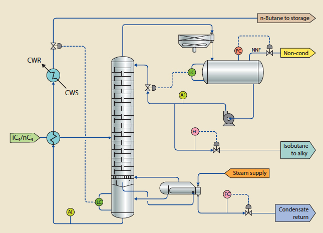
Figure 1 Butane splitter flow scheme
Column operation was reported to be steady. Previous tower scans showed no evidence of flooding. The tower appeared to be reboiler limited since increasing steam flow beyond a certain point resulted in condensate flow meter instability and control valve swings. The amount of isobutane in the bottoms was significantly more than the 1999 design prediction, even at charge rates well below design. Because the tower pressure had to be set high enough to allow the bottom product to be pressured out to storage (approximately 100 psig), the tower seemed to have excess condensing capacity.
Ascent collected data sheets and mechanical details for all equipment in the system. The client provided operating data from the DCS system and product analyses from the laboratory.
Initial Calculations and Test Run
With this information in hand, we proceeded to evaluate all aspects of the system. Tower operation was simulated and rigorously verified against the operating data. Tray and tower drawings were closely reviewed, and flooding calculations were performed for the trays. The tower control system and logic was reviewed. The reboiler and condensers were rigorously rated. A nozzle elevation review revealed that there was little static head driving the reboiler flow, so detailed hydraulic calculations for the reboiler circuit were performed.
The initial simulation results and equipment calculations showed that the tower’s performance with existing equipment was much worse than calculated. The primary issues identified were hydraulic limitations with the reboiler piping and issues with the control scheme and operating philosophy. Tray flooding was found to be unlikely, though low tray efficiency (which had been previously identified by the client) was confirmed to be a problem.
A plant test was scheduled to determine whether changes in operation could improve tower performance immediately. Gamma scans of the tower were also scheduled to see if the trays were prematurely flooding and to help confirm the conclusions made regarding the reboiler piping having insufficient head. The results of these tests were used to develop the final scope of modifications recommended to improve tower performance, maximise isobutane recovery, and maximise refinery profit.
Operating Strategy and Controls
The tower control scheme is included in Figure 1. The distillate product is on regulatory flow control, as is the reboiler steam flow. On-line analysers allow the console operator to monitor purity of both products.
The operating strategy for the tower was reviewed. It was learned that the console operator’s first priority was to adjust manually the distillate rate to maintain approximately 5% nC4 in the isobutane distillate. Secondly, the reboiler steam condensate rate was set at a conservative value that was stable and kept the tower overhead fully condensed. The console operator tended to vary the reboiler condensate rate set point with tower charge rate, and at lower charge rates the reboiler steam flow was significantly lower than the observed limit. Finally, the tower pressure was set as low as possible. Note that this is a ‘non-material balance’ type of control scheme, which does result in stable operation, but is not recommended unless other control schemes have been proven to be unsuitable.1 This control scheme may have been a holdover from the previous service, before the tower was converted into a butane splitter.
With the distillate product rate fixed, the tower suffered from poor product purity control. To illustrate the problem, consider a tower feed that is 5000 b/d of isobutane and 5000 b/d of normal butane. If the operator sets the distillate rate at 4900 b/d, then the distillate will be nearly pure isobutane if there is adequate reflux, and the 5100 b/d tower bottom product will have some small percentage of isobutane. If the tower feed rate drops to 4000 b/d of each component, and the operator does not change the distillate rate set point, the 4900 b/d distillate will become contaminated with 900 b/d of normal butane. Similarly, if the tower feed jumps to 6000 b/d of each component, 1100 b/d of isobutane must leave with the bottom product unless the distillate rate set point is changed by the panel operator. Similar results occur if the feed composition changes instead of the feed rate.
This mode of operation can be seen in Figure 3, which shows considerable variation in bottom product isobutane concentration at any given tower charge rate. The console operator had to make manual adjustments to the reboiler duty and distillate flow rate in response to changes in feed rate and composition resulting from changes in crude slate or SGP operation.
It should be noted that this type of scheme can work with continuous operator intervention. However, this column was only one part of a larger operating unit, and so the butane splitter received reduced attention. As would be expected, this resulted in frequent operation at less than optimum conditions since the ‘non-material balance’ type of control scheme required frequent operator intervention.
Maximum separation occurs when the reboiler and condenser duties are maximised bringing the vapour and liquid flows up to the limits of the column diameter, no matter what the tower charge rate is. This duty-maximising mode of operation is illustrated in Figure 2 which shows how separation could be improved by increasing reboiler duty and column traffic at a higher pressure.
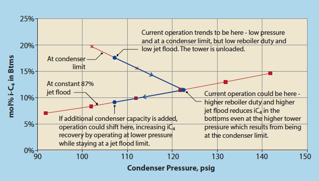
Figure 2 iC4 in Btms vs pressure and jet flood at constant charge
This concept was applied during the test run, and the results showed that current operation could be markedly improved. During the test run, the reboiler steam flow was set near the observed limit and was not adjusted for changes in tower charge rate. The tower pressure was allowed to increase as required to maintain total condensation of the overhead vapour. The distillate composition was continually monitored and the distillate rate adjusted as needed. As Figure 3 shows, the isobutane recovery was improved, particularly at lower charge rates. Whereas previous operation at a low charge rate might have seen 12-17% isobutane in the tower bottoms, the changes in operating strategy resulted in 5-10% isobutane in the tower bottoms. With no capital investment, isobutane recovery was markedly improved. At higher charge rates, the data shows that the test run results were similar to typical operation. Thus the column was shown to be ultimately limited by its hardware rather than by its control scheme.
Looking for a permanent solution, it was desired to convert the control system into a ‘material balance’ type scheme which would allow the control system to automatically maintain product purities by adjusting the tower material balance in response to feed rate or composition changes. The chosen control scheme2 is very close to the existing control scheme, only needing a new control variable to use as the basis for adjusting the distillate flow. A typical overhead temperature control system was reviewed and rejected, with the tower overhead temperature too insensitive a variable for good control, particularly in light of the operating pressure variations expected from day to night and summer to winter. The existing on-line distillate analyser was deemed accurate and reliable enough to cascade to the distillate flow controller, and this was recommended to provide the desired material balance and composition control.
An advanced process control (APC) system for the butane splitter existed, but its use had been discontinued. Ascent recommended the APC system be put back into service. The APC could be used to implement the strategy of maximising the reboiler duty up to a tray flooding limit at all times and minimising tower pressure only after the reboiler and tray limits had been reached.
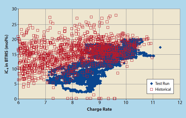
Figure 3 Charge rate vs iC4 in bottom nC4 product
Trays
The tower was simulated to match the observed flows, temperatures, and purities. The number of theoretical stages in the tower was adjusted to match the observed product purities and reflux rate. The existing high capacity trays were rated using the simulation results and found to be lightly loaded at approximately 57% of flood. This result was confirmed by several gamma scans made while the tower was at lower feed rates, which showed no signs of flooding.
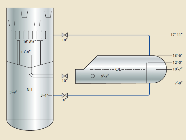
Figure 4 Kettle reboiler piping and elevations
Despite the lack of flooding, the efficiency of the existing trays was a concern. The efficiency was estimated to be approximately 73%. This was roughly in agreement with a previous 2001 estimate of 68% efficiency, and a vendor estimate of 70-75% efficiency for this type of tray. The observed tray efficiency is lower than typically expected for a iC4/nC4 system, which could reach 100% or more with conventional trays. Tray efficiency is crucial in this system and similar systems with relatively close boiling points and low relative volatility difference. This is particularly true for this tower, since the number of trays is on the low side for a typical butane splitter.
It was determined via simulation that new, higher efficiency trays would increase the isobutane recovery with no other changes to the tower. An increase in tray efficiency from 73% to 85% would reduce the isobutane in the bottom product at design conditions from 24.5% to 22.6%. This would result in an estimated $1 million annual benefit to the refinery, which justified a complete retray. A different type of high capacity tray, expected to have a higher efficiency, was recommended even though the capacity increase over the existing high capacity trays was marginal.
Reboiler Review
The butane splitter utilises a kettle type reboiler that is intended to take the total liquid coming from the chimney tray as its feed. Steam that is let down from 175 psig to approximately 55 psig is used on the tube side to heat the process liquid. Concerns about the reboiler were expressed at the project kickoff meeting, and it was noted that the reboiler was considered to be a column limit. Several aspects of the reboiler system needed verification to ensure the performance required.
As previously mentioned, the maximum reboiler steam rate was limited. Beyond this limit, the condensate flow became erratic and the steam control valve would swing. During the test run, the steam let-down valve was swinging between 55% and 65% open, with the reboiler supply pressure then varying from 52 psig to 60 psig. The condensate valve varied from 32% to 38% open during this time. It appeared the reboiler could not condense any more steam past the observed maximum rate, at which point steam would blow through and the condensate flow became two-phase. Trying to measure two-phase flow with an orifice plate resulted in erratic condensate flow meter output and unstable operation. Also, with steam blowing through the exchanger and the condensate level control valve no longer maintaining back pressure, the steam chest pressure in the reboiler dropped, reducing the LMTD available and therefore limiting heat transfer.
Initial thoughts were that the reboiler was under-surfaced. Lack of surface area could have been the cause for the inability to condense more steam and provide more reboiling duty to the tower. From the symptoms observed, concluding the reboiler was fouled instead of under-surfaced (or under-surfaced because of excessive fouling) is also perfectly reasonable. However, other possibilities needed evaluation as well. A poorly designed condensate system, improper condensate flow meter installation, and reboiler hydraulics were all possibilities to be considered.
The reboiler was thermally rated and was found to be approximately 67% over-surfaced at project design conditions, even with a conservative fouling factor. The over-surface was much higher at the observed operating conditions, which had a lower charge rate and lower reboiler duty. The conclusion drawn from this review was that the reboiler size was adequate, fouling was unlikely to be limiting the reboiler, and the cause of the reboiler issues lay elsewhere. A recommendation was made to pull the bundle for cleaning during the turnaround, in case it was severely fouled.
A hydraulic review of the process side of the reboiler system was performed. The existing reboiler had a 10” liquid feed line, an 18” vapour return line, and a 6” liquid product line. As Figure 4 shows, a chimney tray collects the bottom tray liquid and feeds it to the reboiler via a standpipe. The relative elevations of the tower and reboiler provided only 4’-8½” of liquid static head to drive the liquid flow to the reboiler and the vapour return flow back into the tower. The bottom tray liquid, primarily normal butane, is very light, and the static head available equated to approximately 1 psi of driving force. The low driving force immediately made this circuit suspect; a hydraulic limitation had a high probability of being a major cause for the reboiler limitation.
Detailed hydraulic calculations of the reboiler feed and return piping indicated that the liquid head available on the chimney tray to overcome the piping frictional losses was marginal for the observed operation, and definitely insufficient for design conditions. The reboiler circuit capacity was estimated to be 950-1100 g/m.
Based on detailed hydraulic calculations, it was hypothesised that a significant amount of liquid was overflowing the chimneys and bypassing the reboiler. A restricted reboiler feed rate would explain the following observed issues around the reboiler:
- As steam to the reboiler was increased, liquid vaporisation in the reboiler reached 100%. Past that point, more steam was being brought in than could be condensed. This excess steam left with the condensate, and the two-phase condensate flow gave an unstable flow measurement which resulted in both the condensate flow control valve and 175# steam let-down valve opening and closing rapidly.
- The reboiler duty could not be increased enough to get the tower vapour load up to the tray flooding limit. The available tower diameter was not being effectively used to separate iso- and normal butane.
- Liquid from the bottom tray, which is richer in isobutane, bypassed the reboiler completely, further increasing the isobutane lost to the bottom product. Once the reboiler reached 100% vaporisation all of the tower bottom product came from liquid that spilled over the chimneys and bypassed the reboiler.
Including a reboiler bypass in the simulation, such that the 175 g/m tower bottom product was composed entirely of bypassed bottom tray liquid while the reboiler vaporised 100% of the 950 g/m fed to it, improved the simulation match to plant data.
Ascent recommended the tower be gamma scanned to verify that insufficient hydraulic head existed to force flow through the reboiler rather than overflowing the chimneys. A liquid level at the top of the chimneys would prove the reboiler hydraulic limitation hypothesis that bottom tray liquid was spilling over the chimneys and bypassing the reboiler. A gamma scan would also check for unexpected tray flooding, help determine if there was equipment damage, and look for any unexpected issues inside the tower.
As expected, the gamma scans showed the chimney tray to be liquid full up to the level of the chimneys at nearly all charge rates. It was confirmed that this was the biggest bottleneck in the tower – bottom tray liquid was bypassing the reboiler because of insufficient hydraulic head, limiting the reboiler duty and allowing excess isobutane to escape into the bottom normal butane product.
The detailed plant match data, simulation, and calculations were thus validated with gamma scans, resulting in complete confidence that a cause had been found and could be fixed with appropriate modifications.
To achieve the required reboiler duty at the new design conditions, which would increase the vapour/ liquid traffic in the tower up to the flood point, a reboiler feed rate of 1600 g/m was needed. To achieve the desired 1600 g/m of flow while maintaining the liquid level on the chimney tray at approximately 50% of the chimney height, the following modifications were required:
- The existing 10” reboiler feed line was replaced with new 16” piping, including new 16” nozzles on the butane splitter and on the reboiler shell. The tower’s internal reboiler draw piping was also replaced with 16”.
- The standpipe on the chimney tray was removed. This eliminated the stagnant volume present below the top of the standpipe and helped reduce the pressure drop. The new 16” reboiler draw was installed flush with the tray deck and a vortex breaker was placed over the new opening.
- The existing 18” vapour return line, reboiler and tower nozzles, and Schoepentoeter were replaced with 24”.
- An impingement plate mounted inside the reboiler shell at the existing feed nozzle was removed as part of the nozzle replacement. A new impingement plate was attached to the tube bundle instead. This increased the open area at the reboiler feed nozzle, resulting in a lower pressure drop through the nozzle.
- Two non-condensable vents were added to the reboiler channel, one at the top of the channel and one underneath the partition plate. The lower vent is typically left cracked open during operation. Venting non-condensable gases such as air and CO2 reduces the risk of corrosion and also improves heat transfer efficiency. The vents also help purge air from the reboiler during start-up.
- In order to improve reboiler control stability, the steam flow control point was moved from the flow meter on the condensate to a flow meter on the steam supply line. Measuring marginally sub-cooled condensate with a flow meter invites flashing and inaccurate measurements as compared to more accurately measuring the single phase steam flow.
Fixing the reboiler feed limitation, with no other changes, was expected to reduce isobutane in the bottom product from 24.5% to 17% at design conditions. When combining the reboiler modifications with new, higher efficiency trays, isobutane in the bottom product was expected to be reduced even further to 13.2%.
Condenser Review
Eight parallel air cooler bays are used to condense overhead vapour from the butane splitter. As discussed previously, isobutane recovery is maximised when the tower is operated at its tray flooding limit at the lowest pressure the condensers can achieve as limited by rundown hydraulics.
The existing air coolers were rigorously rated. Due to improved isobutane recovery, there is an incentive to maintain the tower pressure close to 100 psig during hot weather. This incentive is shown in Figure 2. The rigorous condenser rating showed that an inlet air temperature of approximately 80°F (27°C) was required for the existing condensers to maintain a tower pressure of 100-105 psig when the tower is operating at or near the flood point. At the design air inlet temperature of 95°F (35°C), the existing condensers would maintain the column pressure at approximately 125 psig when operating the tower close to its flood point.
At project kick-off, the condensers were believed to have excess capacity, but current operation was deceiving because of the reboiler limitations. An incentive actually existed to increase the condensing capacity for operation during warm weather.
The following modifications were recommended to increase the condensing capacity during the summer months.
The tubes of all the condenser bays were scheduled to be replaced in kind during the turnaround due to their poor condition. Four of the tube bundles had fin counts of six fins per inch, while the other four bundles used tubes with 10 fins per inch. To maximise heat transfer area within the existing bundle design, Ascent recommended that all replacement tubes be 10 fins per inch.
Rigorous analysis of the exchangers showed that increased air flow was a relatively inexpensive method to increase the condensing duty. Ascent recommended new fans and higher powered motors. Five of the motors included variable frequency drives with automatic controls to improve controllability.
Increasing the condenser capacity, when combined with the other recommended changes, was expected to reduce isobutane in the bottom product from 13.2% to 10.1% at design conditions.
Project Execution
The design portion of the project was fast-tracked, taking just seven months from kick-off meeting to column shutdown. Fast-tracking a capital project within a large organisation can be a project of its own. Clear justification for each piece of the scope to be executed was key in convincing the site to execute the project on such a compressed schedule. A partnership with Ascent and the tray technologists was another key enabler, as the tray rating and data sheets could be developed in parallel to the overhead condensing and reboiler development work. The tower revamp work was to be performed in a running unit, which added safety and constructibility concerns.
Once project execution was initiated, installation of the new trays proved to be difficult and time consuming. Upon entry, the column was found to be out-of-round and the new trays were found to have some fabrication deficiencies. The tray fabrication issues were addressed in a temporary construction shelter at the site, and installation required constant fit-up corrections with the tray panels themselves.
Fitting up the tray panels and getting buy-off from process engineering inspection initially seemed as though it would bust the schedule. However, process engineering ensured quick responses and the tray installers improved fit-up timing efficiency. As new trays were being flown up the tower by crane, the next trays were being modified using a new weld plan and corrected drawings within the temporary construction shelter. This effort allowed the project to meet the original schedule.
Installation of the new, larger reboiler supply and return nozzles in the 50-year-old tower shell also proved to be a challenge. In the end, the reboiler related work required 57% of the total project investment, 25% went to the trays, and 18% went to the condensers.
Revised Operation
Most of Ascent’s recommendations were implemented during the shutdown. The reboiler and condenser modifications described previously were all completed. New high capacity trays of the same type but with efficiency enhancements were installed.
Performance of the tower, as measured by isobutane in the bottom product, improved markedly upon start-up. One set of data taken shortly after start-up showed 14.5% isobutane in the column bottom product at 113% of the design charge rate. This was a considerable improvement on previous tower performance, particularly considering a temporary limitation on reboiler steam supply in place at the time. A review of the refinery isobutane purchases a month after start-up showed annualised savings of $2.6 million. This isobutane recovery benefit did not include the economic impact of being able to blend more butane into gasoline. Longer term post-revamp operation is plotted against pre-revamp operation in Figure 5.
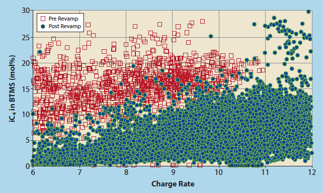
Figure 5 Charge rate vs iC4 in bottom nC4 product, post-revamp
There is still room for additional improvements. The APC was configured and placed into service well after the modified tower had been returned to operation. Some enhancements were made as operating experience was gained, such as increasing the maximum allowable tower pressure drop. When in service, the APC can minimise the isobutane losses, although at times the isobutane losses are not minimised in favour of meeting other objectives. Operations does not consistently use the APC, however, and the reasons for this should be explored.
Conclusion
These results demonstrate the success that can be achieved when all aspects of the system are carefully examined. A detailed plant match simulation and detailed equipment calculations are crucial to identifying the opportunities and solutions. Studies such as this isobutane recovery effort often reveal opportunities for higher throughput, improved operation, and increased profits that were not previously known or considered. In many cases, relatively minor changes often lead to large increases in unit performance and profitability.
References
- Kister H Z, Distillation Operation, McGraw Hill Inc, p492.
- Kister H Z, Distillation Operation, McGraw Hill Inc, p498.
Joseph (Joe) Musumeci is the founder of Ascent Engineering, Inc., Houston, Texas, a process engineering and development firm serving the refining industry. Since 1997, he has been responsible for managing Ascent’s consulting and process design projects, from unit operations support and technical management to troubleshooting, debottlenecking, and grassroots process designs encompassing all refining process units. He holds a BS in chemical engineering from Texas A&M University and is a registered professional engineer in the state of Texas.
John Estill is a Senior Lead Process Engineer with Ascent Engineering, Inc. He has worked on refinery and chemical plant engineering projects since 1991, from conceptual studies to detailed engineering design to troubleshooting. He holds a BS in chemical engineering from Texas A&M University.
Greg Mitchell is Production Technical Supervisor with Shell Norco and was the client process engineer for this work. He has worked in design roles for a variety of projects and has worked in refining production since 2010. He holds a BS in chemical engineering from the University of Arkansas.