Deep Cut Vacuum Towers
Abstract
Deep cut vacuum tower operations can offer significant incentives over existing operations. Defining the exact incentives, capital costs, and payouts requires an engineering study. However, initial project feasibility studies can benefit from simplified analysis. This paper compares deep cut incentives for typical light and heavy crudes, Brent and Arabian Heavy. The resultant yields structures and incentives are compared for the two crudes, and economic calculations presented for various charge rates. Depending on charge rate and degree of improvement, incentives range from 1 to $10 MM/year.
Nontraditional Operating Conditions Offer Significant Benefits For Various Crudes
Running a crude vacuum tower in a deep cut mode can provide economic and operational benefits to the refiner. Fully evaluating these benefits usually requires an engineering study. Crude type, furnace, tower, exchanger and vacuum jet equipment all play important roles in the ultimate capacity, low-pressure capability and revamp cost of each specific unit. However, a simplified analysis can benefit initial project feasibility reviews. Economic judgments can be made to determine project feasibilities and potential project payouts. Accurate feed characterization and effective process simulation are key factors in evaluating the deep cut option.
Deep cut incentives for typical light and heavy crudes, Brent and Arabian Heavy, are compared. Analyzing resultant yields and payouts establishes economic calculations for various charge rates. This technique is valuable in determining project potential and equipment requirements. By examining deep cut concerns, a structure for benefit and risk analysis can be developed.
Background
Vacuum towers are one of the simpler refinery units since they are not a conversion unit like a hydro-cracker or FCCU. However, vacuum units are important because, along with crude units, they process all of a refiney’s incoming crude. Crude and vacuum unit performance affects all downstream operations.
Vacuum units have improved over the years. Originally, many vacuum units had trays for mass transfer. In fuels type vacuum towers where low pressures improve heavy vacuum gas oil (HVGO) recovery and profitability, trays gradually were replaced with random packing. The packing had lower pressure drops than trays, reducing flash zone pressures and overall column pressure drop. In the ’70s and ’80s, structured packings were successfully installed in many units. Structured packing has an even higher capacity than random packing and is now the dominant contacting device in vacuum service.
Improved vacuum tower operation meets the demands of the ever-heavier world crude slate. Better technology and operation not only accommodate heavier feeds, but allow yield improvements by upgrading residue to HVGO. Increasing HVGO recovery provides a large economic incentive per barrel, and may reduce the need for capital expenditure. Reducing residue production through deep cut vacuum tower operation helps mitigate the effects of heavier crude slates, reducing the need for additional residue processing capacity like coking.
Deep Cut
These operations are characterized by increased gas oil yields and lower column bottoms flowrates. For a vacuum tower, this means a higher residue initial boiling point and greater HVGO production. Because traditional crude vacuum fractionation columns deliver a HVGO/residue cut-point of approximately 1,050 Fahrenheit, deep cut operation is considered to commence when higher cutpoints are implemented. However, many vacuum columns operate at cutpoints below 1,050 Fahrenheit. These units may benefit greatly from higher cutpoints. Cutting deeper into the bottoms to recover desirable product is not a new strategy for any fractionation system. Increased product recovery has always been beneficial to profit enhancement. However, vacuum column operations present an arduous environment for efficient fractionation, which makes upgrading product from bottoms to distillate more difficult than other services.
There are many challenges to atmospheric bottoms vacuum fractionation. High heat removal requirements make pumparounds a necessity. These zones require column height but reduce separation efficiency. Coking and column feed thermal degradation must be managed to ensure efficient and continued equipment operation. Generating and maintaining a vacuum for column operation is often a constant battle. Even with these problems, cutting deeper into the vacuum bottoms product to recover valuable gas oil product is increasingly practiced. This is partially due to technology development. Vacuum tower fractionation technology has improved with better structured-packing options, more knowledge about their operation and coke formation mitigation. Not only distillation technology has improved–conversion units such as FCCs are better equipped to handle heavier gas oil feeds. Ways have also been found to debottleneck these units and raise their yields, increasing the demand for feed. Finally, refinery crude feeds have been getting increasingly heavier. This trend raises the importance of distillate production and of downstream conversion capacity. These factors combine to focus attention on the potential for deep cut operations.
Simulation
Today’s process simulators are powerful tools for evaluating processes and designing facilities. Many plant revamps and almost all new designs begin with a computer model of the existing or planned process. This model allows the examination of process parameters, whatever if scenarios and equipment requirements. Deep cut operations are candidates for process modeling like any other system. These models provide for low risk economic and facilities requirement analyses. A technical evaluation of an existing facility being considered for a deep cut upgrade should include a process simulation.
Component Characterization
One aspect of modeling is especially pertinent to vacuum system simulation–feed heavy component characterization. Typically, the heaviest portion of a crude feed is the least likely to be understood or accurately represented in a computer simulation. This is partially due to the difficulty in analyzing heavy materials. High-boiling-point, high-molecular-weight hydrocarbons that are messy in the refinery, are even less forgiving when introduced into laboratory equipment. Special requests and justifications are often needed to obtain desired analyses. Additionally, heavy components are usually not extensively examined because the vacuum bottoms’ properties are normally not as critical as those of distillates. The bottom is the bottom–you get what comes out. However, if the goal is upgrading bottoms to gas oil, as with a deep cut scenario, the importance of representative heavy fraction data increases.
Characterizing the heavy fractions of a deep cut candidate feed is important for a number of reasons. The first deep cut question to be asked may be “How much potential gas oil may be recovered from the residue?” Assay data may not be detailed enough to supply accurate yield data. Additional testing is probably necessary.
After the volume of potentially available gas oil is assessed, the material’s composition should be examined. Its aromaticity, metals content, sulfur content and nitrogen content should be evaluated. Again, assay data may not be adequate for the detail required and supplemental tests are probably needed. The heavier crude fractions typically contain increasing concentrations of these components. If possible, establishing a boiling point distribution of these and any other important contaminants assists deep cut prospect analysis. These data can be inserted into a process model as pseudocomponent properties that are evaluated like any other physical property. This allows design optimization relative to contaminant risks concurrent with yield evaluations.
Within the process simulation, it is important to ensure that there are sufficient pseudocomponent cuts in the HVGO fraction region. Typical algorithms for separating an assay into pseudocomponent cuts place decreasing value on increasing boiling point. Ordinarily this strategy speeds computation by reducing the number of components. However, if the assay region under scrutiny is not broken into enough cuts, model output may not accurately represent reality.
Molecular Weight Estimation
This is another area in which the simulator may require special attention.
Deep cut operations often result in a vacuum tower bottoms product that is equivalent to a bunch of bigrocks. The bottoms product molecules are large and bulky. This is especially true of heavier crudes that are often considered for deep cut operation. Accurate molecular weight characterization is critical to reliable equilibrium evaluation. Once again, special analyses may be required to gather sufficient data. If an existing plant is being reviewed, a process simulation of the current operation may be used to better approximate heavy end molecular weights. This is done by altering model molecular weight correlations or values until operating parameters, especially vacuum column bottoms temperature, are met.
Even if accurate laboratory molecular weight data are obtained, using available existing plant data to confirm and fine-tune the information is recommended. Molecular weight correlations supported by computer simulators vary widely and can change from version to version. In addition, they yield strikingly different results. There is substantial variation between the methods, which suggests review is required in any vacuum column model.
Study
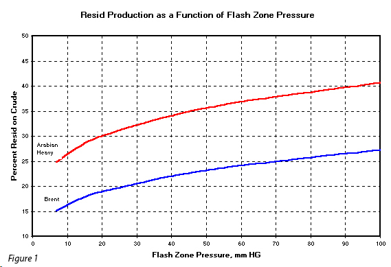
Deep cut incentives for two major export crudes–Brent and Arabian Heavy are compared. Brent (38.3 Degree API) is a typical light crude, while Arabian Heavy is a typical heavy crude 27.4 Degree API). Product yields and properties were approximated using a computer model of a crude and vacuum column. This type of analysis is useful for preliminary examination of project economics. Simulations done for this presentation use assays from literature (n1, n2). Crude column side products are steam stripped and the vacuum column operates without steam stripping. Model operating parameters were varied in examining several operating effects. Results are presented graphically for interpretation. Vacuum column flash-zone pressure and column total pressure drops have significant operating and yield impacts.
Figure 1 illustrates the effect of reducing the flash-zone pressure at constant flash-zone temperature on residue production for both Brent and Arabian Heavy crudes.